Electronics Bring-Up
At this point, everything should be ready to be connected together. We have made extension cables where we need to.
It’ll be great if you had a multimeter right now to do some tests.
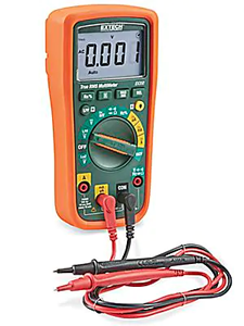
If everything goes right, then you won’t need it. If something goes wrong, we can use it to identify bad connections or bad parts. An infrared thermometer would be helpfun, or even a thermal imaging camera.

We will do this step by step and test after each step. This will prevent any power issues from blowing up any sensitive components. Keep a fire extinguisher near by.
Do not leave the area if the power is on or if something is hot. Do not touch any wires or connectors if the AC power cord is plugged in. Never use your feelings to check temperature.
Skill: Continuity Checking Wires
You can easily check if a wire is broken with the multimeter’s continuity check function. Also, you can also verify the wiring of a heating element before plugging it in, by measuring its resistance value at the end of the wires. Review lesson 9 to see what resistances you should be getting.
Skill: Swapping Wires in a JST-XH Connector
When you have a JST-XH connector that has wires in the wrong order, there’s a way to re-arrange that order. You need a pointy tool to pop out the crimp inside the connector housing. Once the crimp is removed, simply re-insert it into the housing at the correct position.
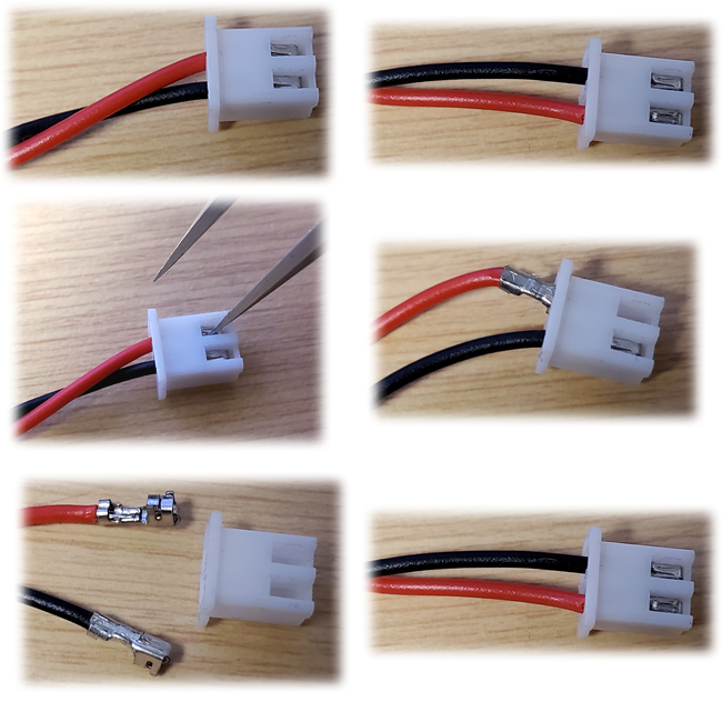
This works on all of our JST-XH female connectors, which includes the stepper motor connectors.
1: Power Supply
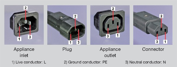
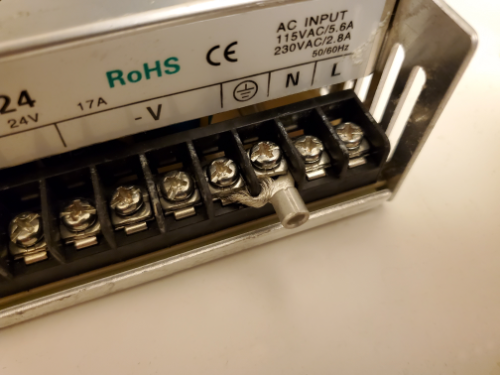
Connect the AC power input to the 12VDC power supply. That means connecting the “Live” (aka hot), “Neutral”, and “Ground” wires.
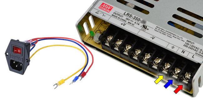
You also need to connect the negative output of the power supply to the ground somehow. This could be a simple piece of bare 14 AWG wire tucked under both the ground terminal and the adjacent V-negative terminal. Recall what we discussed before about grounding.
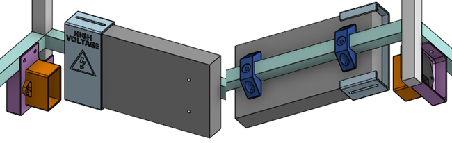
Once the connections are made, mount the AC socket assembly and the power supply to the frame of the printer. The power supply mounts to the frame using 3D printed clamps, M5 flanged screws fastens the clamps to the frame, and M4 screws fastens the power supply to the clamps. Remember to slip on the 3D printed safety cover for the power supply, which is also secured with M4 screws through the slots on the safety cover. The safety cover for the AC socket assembly has cavities for M3 square nuts, which is used to fasten the assembly via M3 screws. If you need countersink M3 screws, you can still use button head M3 screws, because there’s not a lot of forces involved.
When you are ready to power up, keep the area clear, plugin AC power and turn it on. There should be a small LED that lights up on the power supply.
If you can, measure the DC output, it should be about 12V.
Keep it running for 10 minutes. No smoke should come out, nothing should be warmer than 45°C. For all the other tests, also make sure nothing smokes and nothing gets too warm.
Turn the power off and unplug the AC power cord.
2: LCD Screen
The control circuit (SKR Mini E3) should be mounted inside its 3D printed box, secured with M3 standoffs and short M3 screws. The lid should be removed. We do not need the cooling fan yet.
The LCD screen should also be mounted inside its own 3D printed box, secured with M3 standoffs and short M3 screws. But before you tighten down the screws, connect the LCD screen to the control circuit with the cable that came with it.
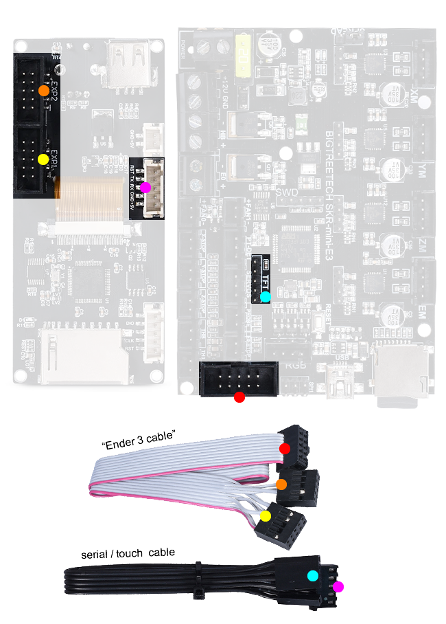
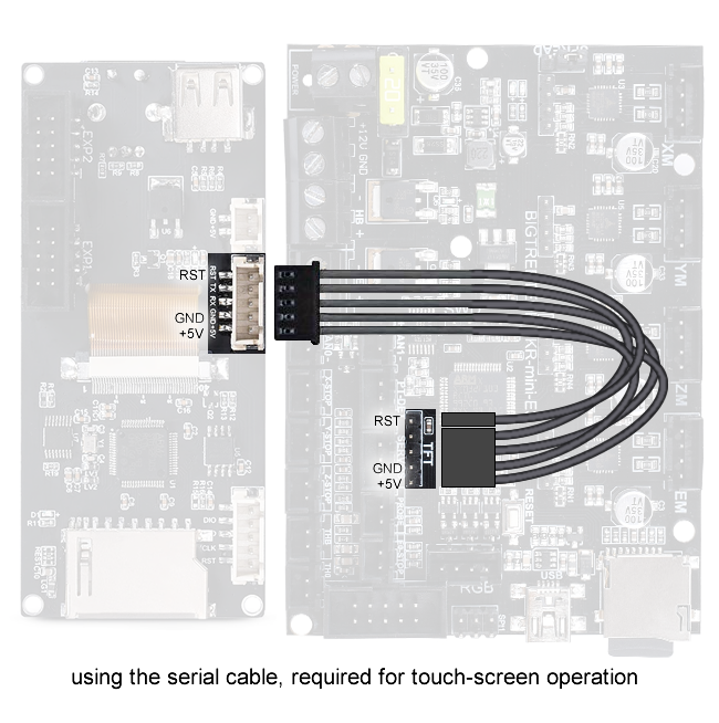
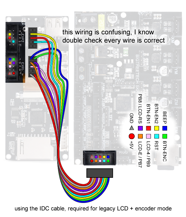
Be really careful about plugging in the cables the right way! BigTreeTech seems to have put some connectors backwards. So I made those diagrams extremely detailed, follow every wire in the diagram to make sure the connectors are orientated correctly.
3: Power Supply to Control Circuit
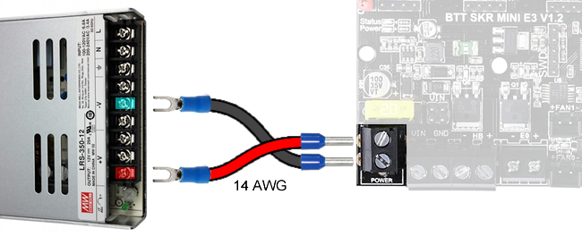
Connect the power supply to the control circuit using the 14 AWG wires we prepared before already.
Turn the power on, LEDs will start coming on and the LCD will start to show stuff (or at least light up as well). This is good. There’s a chance that nothing on the LCD actually does anything when you press it though, don’t worry, we’ll configure the firmware later.
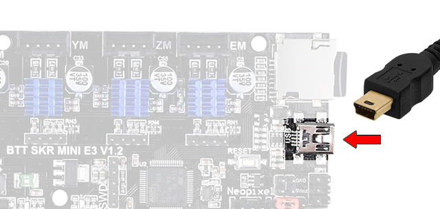
Plug in a USB cable between the control circuit and your computer.
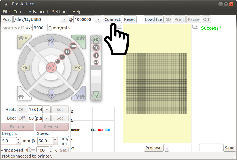
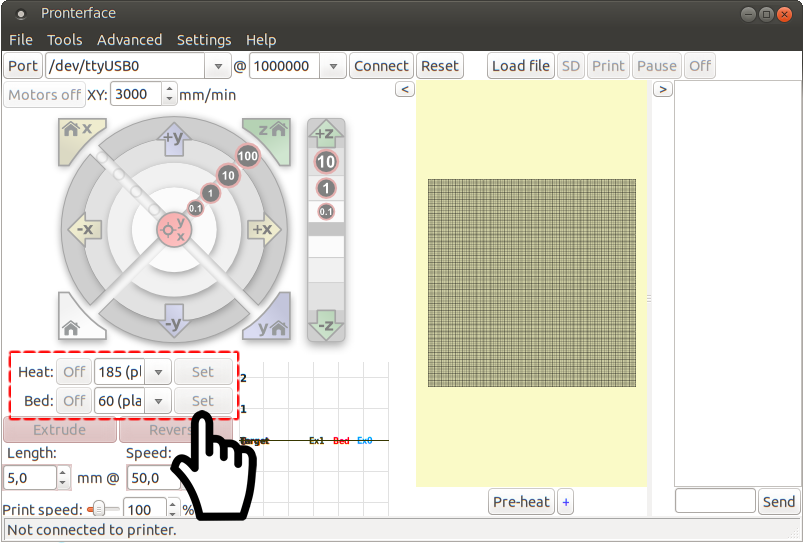
Install all the drivers you need (check manufacturer’s website). Download and install Pronterface, run it and see if you can connect to your control circuit.
Turn the power off and unplug the AC power cord. Unplug the USB cable.
NOTE: The default firmware for the SKR Mini E3 should have been written for a Creality Ender 3 printer. We are using very similar components so things should work out-of-the-box. But we do need to reconfigure things later.
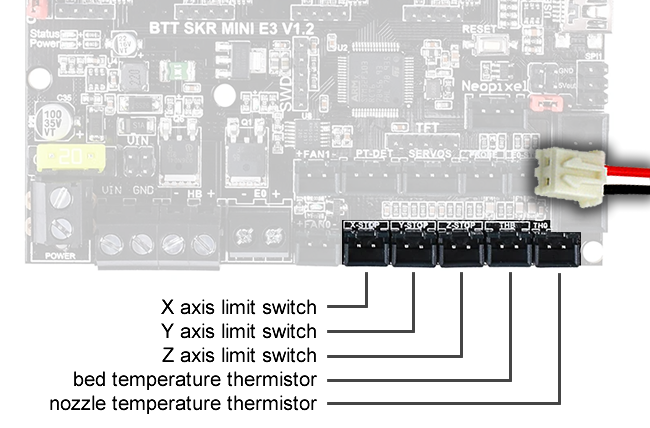
4: Sensors and Switches
Input devices, like sensors, are low power, so we test them first. Plus, we depend on the temperature sensors to keep us safe when we test higher powered devices like the heaters.
Connect all the sensors and switches to the control circuit. You’ve already made all the extension wires for them.
Connect the USB cable, and power on the AC power. Connect to the control circuit from your computer using Pronterface.
You should see that the temperature sensors report values, both the nozzle temperature and bed temperature. Now, use your hot air gun, heat those sensors up and watch your computer screen. Does the values start to increase? If so, then good, test passed. Do this for both the nozzle and the bed. Also when you turn off the hot air, see if the values start to decrease.
The values might be reading room temperature but if they are not, then that could just mean we need to tweak the firmware.
Inside the Pronterface console, type in the following command, then hit send (ENTER key)
- M119
This is the gcode command for “Endstop States”, and it will report when the limit switches are activated. Start pressing those switches, and while the switches are closed, issue the command again. See if the console shows the proper response.
If you are seeing weird behaviour, then disconnect the wires and use tweezers to short circuit the respective connector on the circuit board. Shorting the limit switch connector will make the firmware think the switch is pressed. Shorting the temperature sensor pins should make the firmware think the temperature is very high.
When you are done, turn everything off and unplug everything.
5: Fans
Connect the fans, we’ve already made the extension wires and splitter wires we need. But we need to watch out for which fan is connected to which connector. Follow the diagram.
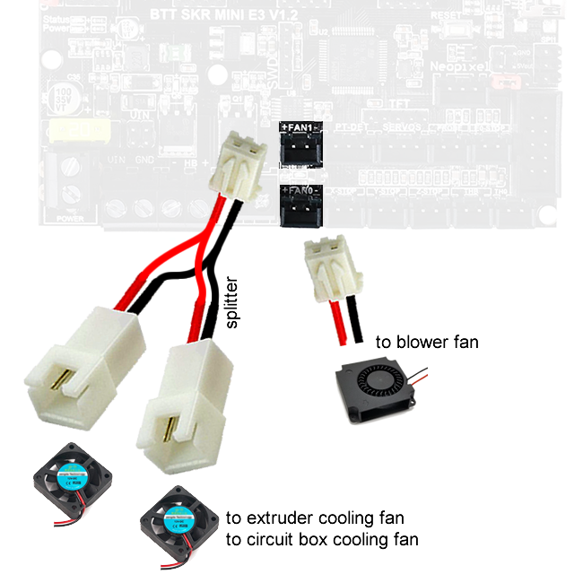
Next we need to check the polarity of the blower fan. The circuit board with have plus (+) and minus (-) symbols, plus means positive and minus means negative. Red wire should go to positive, and black wire should go to negative. If the JST-XH wire colours do not match the polarity shown on the circuit board, then we need to swap the red and black wires inside the JST-XH connector housing.
Power everything up and connect via Pronterface. As soon as power is applied, the extruder cooling fan and the circuit box cooling fan should both start spinning (FAN1 is a “always on” fan on this circuit board). This is good. If they don’t turn on, the wiring has a problem or the fans are broken.
Issue the following command:
- M106 S255
Did the blower fan turn on? If so, then we will turn it on at half speed (FAN0 can be PWM controlled), issue the following command:
- M106 S128
Did the blower fan slow down? Now turn it off with the following command:
- M107
Did the blower fan turn off?
If you are troubleshooting a problem with a multimeter, check that the fan output pins on the circuit board are outputting about 12V when you tell the fan to turn on, and outputting 0V when you tell the fan to turn off.
When you are done, turn everything off and unplug everything.
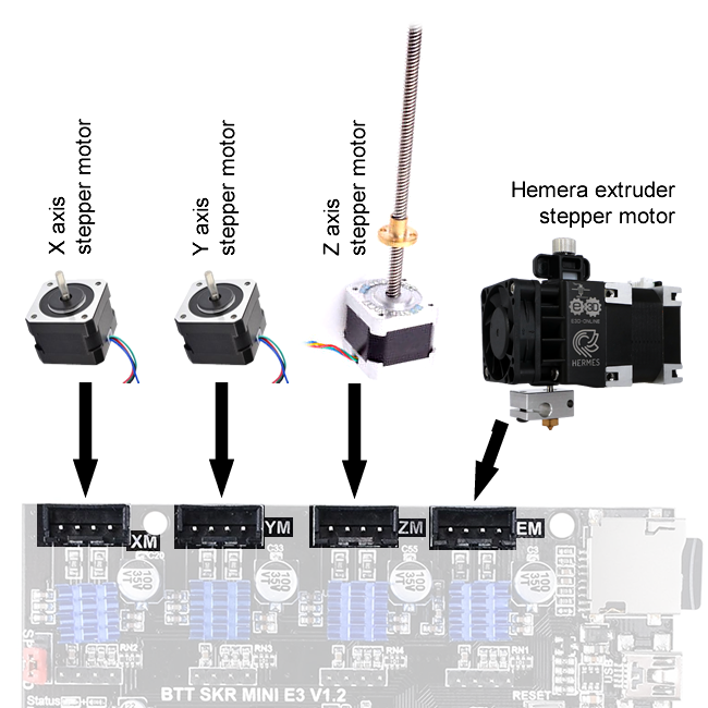
6: Stepper Motors
With everything powered off, AC power unplugged, use your hands to move the print head to the middle of the bed, and move the bed vertically to the middle height of the printer. In this position, it is safe to spin the stepper motors slightly just to check if they work.
With the positions set, now plug in the stepper motors into the control circuit. Double check the colours of the wires. Do not ever connect or disconnect stepper motors while the machine is powered on!
Power everything up and connect via Pronterface.
First, issue the following command:
- M302 P1
(the above command allows for the extruder motor to spin even if the hot-end is cold)
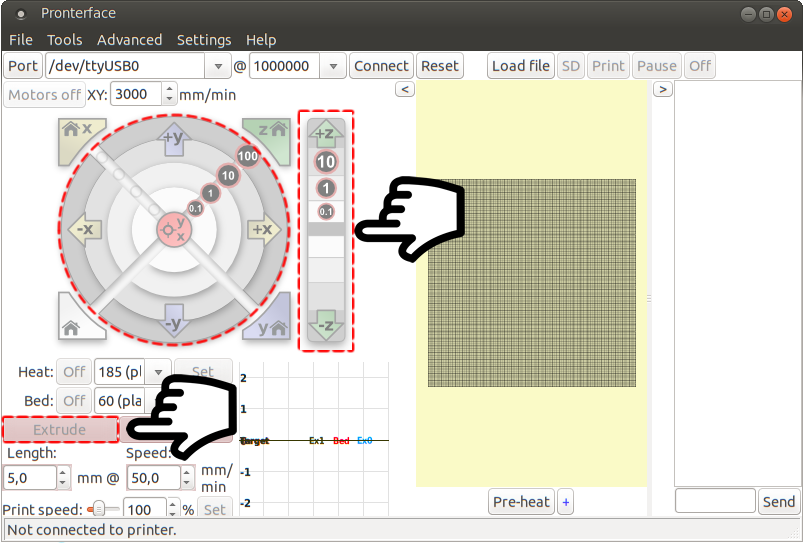
Use the movement interface to move the print head and the bed, do so with only 10mm increments and a slow speed.
- Z minus means the bed moves up, Z plus means the bed moves down
- X minus means the print head moves left, X plus means the print head moves right
- Y minus means the print head moves towards you, Y plus means the print head moves away from you
- press extrude to spin the Hemera’s stepper motor, the gears should turn in a way that extrudes plastic
Do all the motors respond? They don’t have to move in the right direction, they just have to move to prove our wiring is correct. We can flip the direction later when we configure the firmware. But remember which ones need to be flipped.
If a motor is not moving, or only twitching, making a noise, then we need to check the wiring. Power off the printer and unplug the power cord. Unplug the offending stepper motor cable from the control circuit. Check the resistance between red and blue wires, then check the resistance between the black and green wires. The resistance should be close to the coil resistance specified in the stepper motor’s datasheet. If the resistance is too high or infinity, then the wire has a bad connection somewhere. If the resistance is too low, like, zero, then there may be a short circuit somewhere.
If both of these checks pass, then you may simply need to swap some wires around. Rearrange the crimps inside the JST-XH connector to swap the red wire with the blue wire.
Reapply the power and try again. Assuming your connections are good. When you are done, turn everything off and unplug everything.
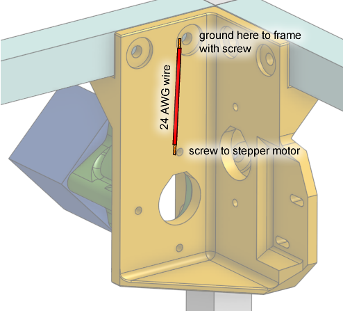
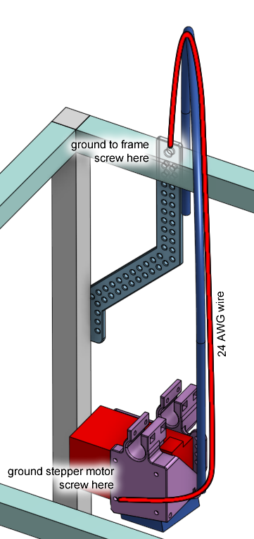
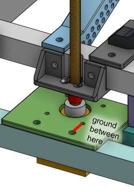
Ground the Stepper Motors
There are four stepper motors in this design that are mounted to plastic, which means they are not grounded (click for prev lesson) to the printer’s aluminum frame. This is not a problem in terms of getting shocked by 120VAC (the 120VAC would need to break the power supply first, then toast the motor drivers in a weird way). But there’s a small chance that static electricity could build up and give you small annoying shocks once in a while, if you are printing in a very dry area.
The easiest way to ground the motors are to use 24 AWG wire to connect the screws between the holes in the following few diagrams. The wire’s ends can be stripped without any connectors.
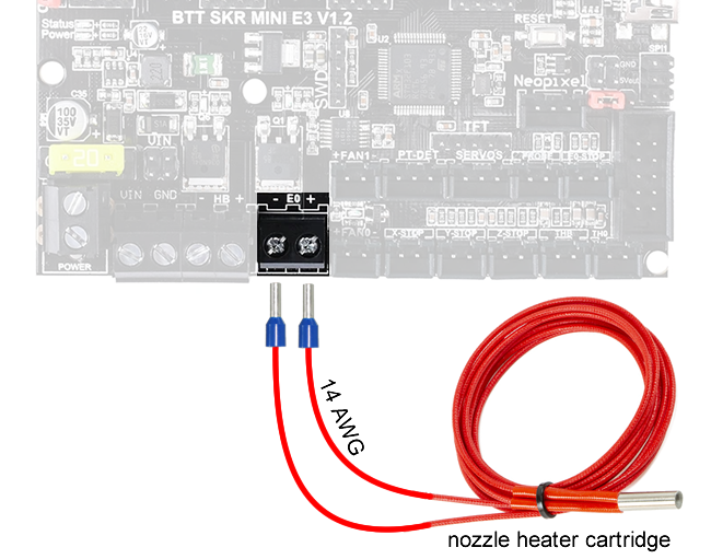
7: Nozzle Heater
Before this step, you must properly re-compile the firmware and flash the firmware to the control circuit. See the page about the firmware (click here). We need the temperature sensor to keep everything safe while we test the nozzle heater, so the temperature sensor must be properly configured before we start. Also, the nozzle heater must be installed inside the heat-block of the hot-end before initiating this test! Otherwise, the thermistor won’t detect if the heater is indeed working.
Connect the nozzle heater wires, already prepared with ferrules, to the control circuit.
Make sure the nozzle is at ambient temperature. Power up and connect up Pronterface. Issue the command:
- M303 E0 S200
This will initiate PID autotune for the nozzle heater. It will start heating up, and when it reaches a certain temperature, it will cool down. It will go through this cycle 5 times automatically. The timing measurements and temperature measurements will be used to automatically computer the PID parameters used by the printer to keep a steady nozzle temperature. When it finishes, it should cool down and output the PID parameters to the Pronterface console, write it down. Then run the command:
- M500
Which will save everything to non-volatile memory.
If anything seems weird, if any connectors or wires start smoking or melting, disconnect the power immediately. When you are done, turn everything off and unplug everything.
If the temperature does not rise, disconnect the power and start investigating the wires.
8: Bed Heater
Before this step, you must properly re-compile the firmware and flash the firmware to the control circuit. See the page about the firmware (click here). We need the temperature sensor to keep everything safe while we test the bed heater, so the temperature sensor must be properly configured before we start.
Connect the bed heater wires, already prepared with ferrules, to the control circuit.
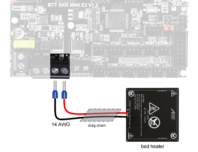
Make sure the bed glass is affixed to the bed heater with binder clips. We need the glass to act as a thermal mass, a sponge for heat. Once everything is ready, move on to the stress test, which is when we will power up the bed.
9: Electrical Stress Test
First, remove the box cooling fan from the circuit box. Don’t disconnect it, just remove it.
Get your test gear ready, and have a fire extinguisher (must handle ABC type fires) near by.

Then, power everything up and connect to the printer via Pronterface. Before we start, make sure you’ve done the autotune for both the bed heater and nozzle heater already, the saved PID values will be loaded when the control circuit powers up.
Command the bed to heat up to 80°C, and command the nozzle to heat up to 250°C.
Leave the printer running like this for an hour or two. Check the temperatures of all the connectors and wires, nothing should reach dangerous temperatures during this time. You can check once every 15 minutes, read a book, but sit beside the printer.
If something on the circuit board gets warmer than 60°C, then install the cooling fan back into the box and continue the test.
The temperatures of both the bed and nozzle should rise to the target within 10 minutes. If one or both of them do not rise, then something is wrong, and most likely, the safety feature called thermal runaway protection will kick in and the heating will stop automatically. If the temperature does rise but do not reach the target fast enough, it means there’s not enough power being fed into the heater. It could be a bad PID value, or bad wiring, or bad heater, or you are in a very cold room.
NOTE: Typical 3D printing of PLA filament is done at a nozzle temperature of 200°C and a bed temperature of 60°C, we are using higher numbers for testing because we are stress testing.
Turn off the power and unplug the power cable when you are done.
Finishing Up
Close up the circuit board box with the lid. Mount everything to the frame if you haven’t already. Use zip-ties to secure all wires to the frame somehow, take advantage of the T-slots. The wires running up to the extruder should be zip-tied against the teflon tube.
Congratulations! You’ve just built a 3D printer!
The next steps are to: